
Project Task - the Wire
We encounter motor skills issues (slower reaction time, clumsiness and inability to perform certain activities) almost daily. Many of the jobs today require a steady hand. For example, architects, welders, dentists and surgeons must have a “steady” hand for their work to be successful. Motor skills issues are especially pronounced when it comes to the non-dominant hand.
Researches show that 96% of the world population uses their right hand (are right-handed). For the majority of these people, the left hand is completely neglected, and they are unable to perform many activities which require precision with this hand.
One of the ways to overcome this issue is the device called the Wire; with this device, a person can practice motor skills by receiving feedback on the level of success of task execution. With the assistance of this device, everyone can practice their concentration and fine motor skills. Depending on the feedback, the user can determine whether he or she is dexterous, or whether there are some motor skill issues and more practice is required.
For the construction of the Wire device, you will need:
4 Micro:bits
Crocodile clips
Wires of various sizes
Wooden base or styrodur
Speakers or headphones
Clip (hook)
In order to make the Wire device, first, we have to make a device comprised of the wire on which we can practice our motor skills, wooden (or some other) base and Micro:bits.

Procedure for connecting Micro:bits
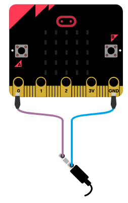
Now that we are familiar with the basic characteristics and components of the Micro:bit, we can proceed with the construction of the Wire device. We should connect Micro:bits using crocodile clips to the configuration mentioned above. We will connect the first Micro:bit by connecting the grounding (GND) to the wire, using crocodile clips. The figure below shows the connection between the grounding and the Micro:bit (only for one device).

Additionally, we have to connect the Micro:bit with the part of the device which tests motor skills (hook). Once the “Wire” device is constructed, it is time to create programs for each Micro:bit.

Programming
Each of the four Micro:bits has to be programmed individually: 1. The first detects and counts the mistakes made by the user 2. The second starts the time 3. The third measures the time 4. The fourth makes a sound when the user makes a mistake.
Step 1
Go to https://makecode.microbit.org/.
Step 2
Create a new project.
Now, we wish to program mistakes detection, more precisely we want to detect, using the Micro:bit, when the hook touches the main wire.
Based on the physical Wire device, we can conclude that the pin P0 is the “trigger” for all events.
Since the P0 pin is connected via the crocodile clips to the hook, the mistake is detected by touching the main wire and the Micro:bit should display a cross (we are programming mistake detection).
Step 3
From the category  choose the block
 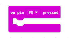 and from the drop-down list choose pin
 P0.
This block will be our “trigger” for the visual display of the mistake.
Step 4
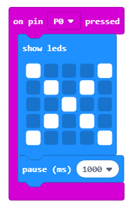
Now, we have to add the block displaying the cross sign on the screen, which will appear when the user touches the main wire with the hook.
Choose the category  and the block
 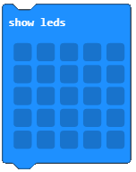 .
.
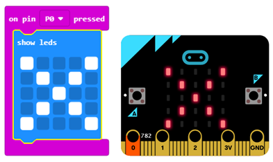
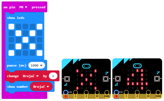
The look of the code and the mistake simulator:
In the code, we will add the block for pause with which we ensure timely system response (Wire device).
Choose the category and the block 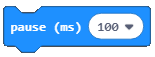 where you can set time in milliseconds (1000 milliseconds = 1 second).
The look of the code:
Step 5
The upper part of the code only shows the detection of the mistake that happens when the hook touches the main wire.
Now, we shall add the part which will count the number of times the user has made a mistake. To fulfill this requirement, we have to find a way to store and, if needed, change the number of mistakes the user makes. Solution for this problem is the introduction of the variable.
A variable can be understood as a space in the computer memory, something like a box, in which, during the execution of the program, we can store some interim values. Variables have names. When we want to use the value of the variable, it is enough to use its name.
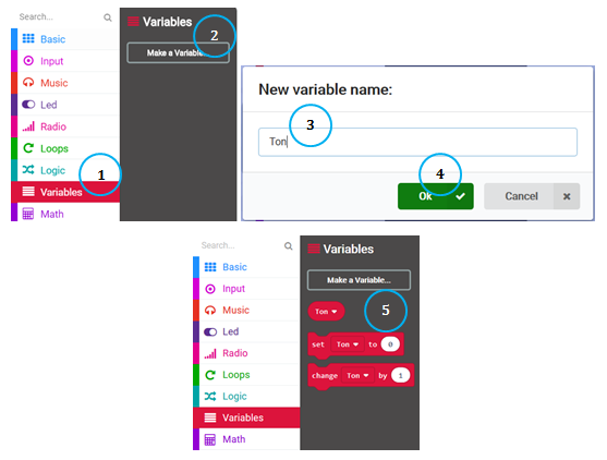
A variable is created in the following manner, in the category Variables (1), click on the button Make a variable (2) and type in the name of that variable in the field (3), in our case the name Counter. By clicking the button OK (4), you have created a variable (5).
Step 6
At the start of the “exercise”, the number on the counter will be 0. Setting the starting value (reset to the starting value) will be defined by the user pressing button A. This means that when the user presses the button on the Micro:bit the counter value will be set to zero, and the counting of the mistakes can begin.
From the category choose the block 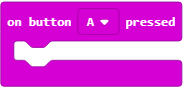 , and from the drop-down list choose button A.
This block will be our “trigger” for resetting the variable Counter.
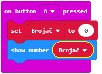
From the Variables category drag the block  .
.
We will connect this block to the block above and with the block displaying the value of the variable. (From the category we choose the block  into which we will drag the block
  from the
 Variables category, and place it in the space with the number 0 written.
This way, we create a block that shows the value of the variable Counter.
Part of the code for resetting and displaying the variable Counter:
Step 7
We can use the variable Counter, whose starting value is set at 0, to count the mistakes. The value of the variable will increase by 1 every time the user makes a mistake, or more specifically, every time the hook touches the main wire.
For this, we will use the block  from the category
 Variables.
We will drag this block into the part of the code in which we have detected a mistake by displaying the X sign.
The look of the code and the running of the code in the simulator:
Step 8
In our next step, we want to upgrade the project by adding the sound every time the user touches the main wire.
For this, we will have to make the connection between two Micro:bits, or more precisely to use the option of the radio communication between them. First and foremost, we have to create the group’s ID, which is used to “create” the space in which, in our case, the two Micro:bits will communicate. To create the ID, we will use the block 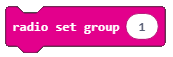 from the category
  . Any number can be chosen. We will leave 1 as the ID of the group. We will then drag this block into the block from the category .
Part of the code, which creates the communication group:
To send a radio signal to another device, which will “react” based on that by emitting the sound when a mistake is made, we have to introduce the following block, into the section of the code that detects and counts mistakes.
Upgraded code for detecting and counting mistakes:
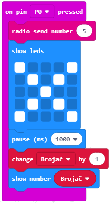
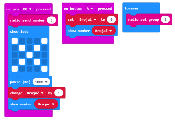
The completed code for the first Micro:bit:
Download the .hex file to your computer by clicking on the button  . The Micro:bit will be ready to start working once you have dragged the file onto it.
Step 9
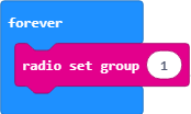
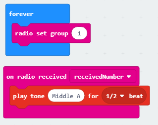
Our next step is to create the program for the other Micro:bit, which will control the sound every time the user makes a mistake. Our two Micro:bits should communicate in the space with the ID group 1.
We drag the block from the category into the block from the category .
Part of the code, which creates the communication group:
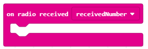
Next step is for this Micro:bit to receive the information (in our case a number) based on which it will “react” by emitting a sound. For this, we will drag the following block from the category:
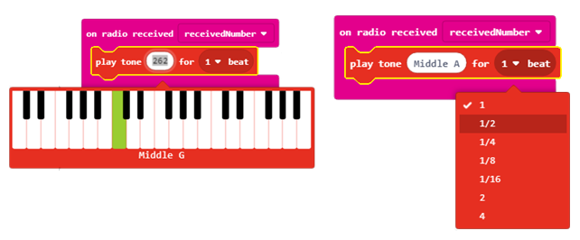
Into this block, we will drag the block  , which reproduces the sound, from the category
  .
From the drop-down list of this block, we will choose the tone and the duration of the tone.
.
From the drop-down list of this block, we will choose the tone and the duration of the tone.
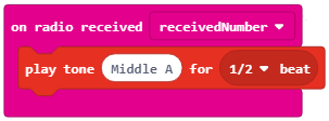
The look of the code, which reproduces the sound:
Note: To reproduce the sound, Micro:bit has to be connected to the speakers or to the headphones in the following manner:
The complete code for the Micro:bit, which has the sound activated:
In this way, we have created detection, counting and sound of the mistakes made by the user when the main wire is touched.
Step 10
To create the device, which will measure how much time the user needs to complete the “exercise” of his motor skills, we have to introduce two additional Micro:bit devices. One will only be a “trigger” starting the clock on the other Micro:bit.
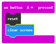
By clicking button A, the device is reset, and the screen is cleared. The reset option is located in the category Advanced - Control.
Option for clearing the screen is in the subcategory More of the category .
Part of the code:
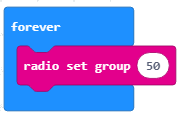
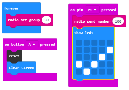
Then we create the space for communication with the ID group 50:
Pin P1 is the pin the hook is connected to via the crocodile clips.
This pin will be used as the time “trigger”. More precisely, the hook touching the wire sends a radio signal, which starts the time. Furthermore, to enable the user to see when the time started, the image  will be displayed on the screen of the Micro:bit.
The completed code for the Micro:bit, which signals the start of measuring time.
Step 11
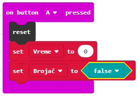
We need to define two variables:
the variable Time with which we will measure the time from the start of the “game”. The game starts upon the reception of the signal from the previous Micro:bit.
the variable Counter which has two possible values true and false – the wire has or has not been touched.
Clicking on button A resets the device and sets the initial values of the variables Time and Counter.
Values for the variable Counter can be found in the category  :
:
The next step is to create the space for communication with the ID group 50:
The P1 pin is the pin the hook is connected to via the crocodile clips. This pin will be used as the time “trigger”:
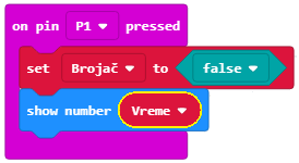
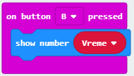
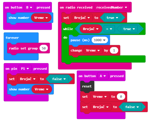
When the user clicks button B, the time it took for the user to complete the “exercise” will be displayed:
When the Micro:bit accepts the radio signal (number) from the other Micro:bit device, the clock starts and the value of the variable Time changes by 1, after every second until the end of the “exercise”:
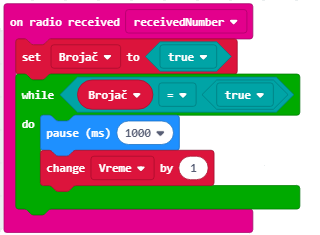
The completed code for the Micro:bit, which measures the time from the beginning of the “game”:
When you have transferred all of these codes to your Micro:bits, you will be ready to “test” your motor skills and begin to “exercise” your weaker hand.